First Impressions
The XBotMicro comes fully assembled, with a set of jumper wires, a handful of plastic standoffs and screws, and a manual in passable, though not always entirely idiomatic, English.
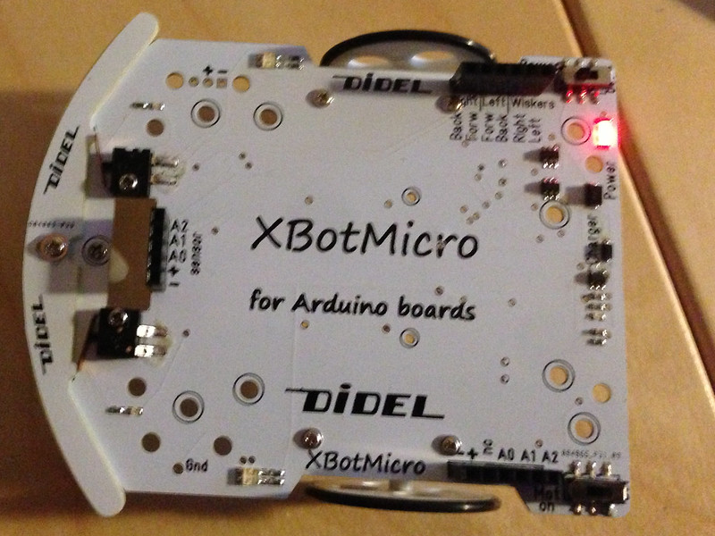
The hardware appears to make a really excellent beginner’s platform:
- Motors and motor drivers built in, just require two microcontroller pins each side to drive.
- Front equipped with solid mechanical bumper sensors.
- LEDs for motors (green/red for forward/backward indicator) and bumpers.
- Built-in LiPo battery, reportedly good for 2 hours’ driving. Very simple charging circuit—if the + pin sees a 5V voltage, the battery gets charged, otherwise, the battery voltage gets applied to the + pin to drive the installed microcontroller.
- Easily accessible power switch—one would think this is a complete no-brainer, but some robotics platforms, e.g. the SparkFun ProtoSnap Minibot Kit, require removing the battery to stop the motors.
- Separate motor switch: This is a really clever feature allowing a dry run of the programming by observing the LEDs, without powering the motors.
Adding a Microcontroller
Naturally, for any nontrivial task, one would want to install a microcontroller. At first glance, I thought that pretty much any Arduino board would do—the XBotMicro certainly looks mechanically compatible with them. However, the devil is in the details: When operating in battery mode, the microcontroller has the LiPo battery, typically about 3.7V, available.
The manufacturer of the XBotMicro makes the Diduino, a rather neat Arduino clone with a built in breadboard. While the Diduino works with 5V, it does not have a built-in voltage regulator, which makes it unsuited to input voltages greater than 6V, but gives it much more flexibility toward LOW input voltages, so the Diduino would work well with the XBotMicro. There are also a variety of 3.3V based Arduino boards, most of which should also work.
Update: It’s been pointed out to me that 5V Arduino boards should also work, as long as the input voltage is applied to the 5V pin, not the VIN pin, thus bypassing the voltage regulator.
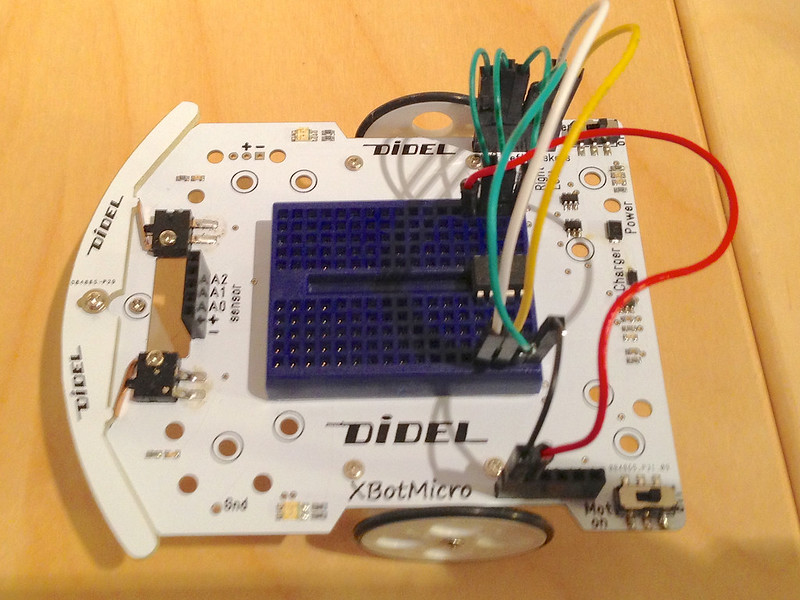
However, none of the Arduino boards I currently own are 3.3V based, so I had to think of another alternative. I ended up putting a self mini breadboard on the XBotMicro and installing an ATtiny84 on it. Since I already hard the Arduino-Tiny core installed, it was quite simple to adapt the demo code to the ATtiny84 and program it using ScratchMonkey. The breadboard has enough room to even implement a dual-ATtiny84 controller solution if I were to need more processing power.
A Minimalist Controller
Once I had this running, I could not leave well enough alone: Why waste the 12 I/O pins of an ATtiny84 on running the XBotMicro if I could save several cents and use an ATtiny85 instead? The ATtiny85 has just the 6 I/O pins needed to drive the XBotMicro (4 outputs for the motors, 2 inputs for the bumpers), provided the RESET pin gets disabled. This requires programming the ATtiny85 using the High Voltage Serial Protocol, but ScratchMonkey handles this just fine, and indeed, the ATtiny85 is perfectly capable of driving the XBotMicro:
Room for Improvement
It would be quite unreasonable to expect a brand new product like the XBotMicro to already be perfect in every way, so here’s a few minor suggestions for improvement:
- The language of the manual is not always 100% clear, and there are some typos.
- I was a bit confused about the A0/A1/A2 pins, initially thinking they were alternate pins for the bumper sensors. The schematics in the documentation are not very clear on that point either.
- The included jumper wires are very short; perfectly sized if an Arduino board is installed on top, but not very flexible for other pinouts.
- The demo code is written in French and is structured a bit awkwardly. I’ve taken the liberty of merging it into a single file and translating it into English.
Demo Code
Here’s my version of the demo code, with pinouts for ATtiny84 and ATtiny85 added (in fact, the code is less than 2K, so you could save a few more cents and run this on an ATtiny25, but I didn’t have any at hand).
This file contains hidden or bidirectional Unicode text that may be interpreted or compiled differently than what appears below. To review, open the file in an editor that reveals hidden Unicode characters.
Learn more about bidirectional Unicode characters
| // | |
| // Demonstrate various behaviors for XBotMicro | |
| // | |
| // Matthias Neeracher: Derived from original XBotMicro demo4, rewritten in English, | |
| // added pinouts for ATtiny X4/X5 | |
| // This code is licensed under the same conditions as the original XBotMicro demo code. | |
| // | |
| #include <Arduino.h> | |
| ///////////////////////////// Pin Definitions ////////////////////////////////// | |
| // | |
| // We define 6 or 7 pins: 4 motor pins, 2 whisker sensor pin, and optionally an LED pin | |
| // (not on ATtiny85) | |
| // | |
| // Motor pins are defined in pairs: If the forward (Forw) pin is HIGH and the reverse (Back) | |
| // pin is LOW, the wheel on that side turns forward. If Forw is LOW and Back HIGH, the wheel | |
| // turns backward. To fine tune the speed, the Forw pins are attached to PWM (analog out) pins, | |
| // so they can change quickly, while the Back pins are attached to regular digital pins. | |
| // | |
| // The whisker pins are active low digital inputs. | |
| // | |
| #if defined( __AVR_ATtinyX4__ ) | |
| // | |
| // ATtiny84/44/24. using arduino-tiny core: https://code.google.com/p/arduino-tiny/ | |
| // | |
| // Pinout is chosen to leave the ISP pins free to simplify reprogramming. | |
| // | |
| // +-\/-+ | |
| // VCC 1| |14 GND | |
| // WhisR (D 0) PB0 2| |13 AREF (D 10) BackR | |
| // WhisL (D 1) PB1 3| |12 PA1 (D 9) BackL | |
| // (RESET) PB3 4| |11 PA2 (D 8) LED | |
| // ForwR PWM (D 2) PB2 5| |10 PA3 (D 7) | |
| // ForwL PWM (D 3) PA7 6| |9 PA4 (D 6) (SCK) | |
| // (MOSI) PWM (D 4) PA6 7| |8 PA5 (D 5) PWM (MISO) | |
| // +----+ | |
| #define BackR 10 | |
| #define ForwR 2 | |
| #define ForwL 3 | |
| #define BackL 9 | |
| #define WhisR 0 | |
| #define WhisL 1 | |
| #define LED 8 | |
| #elif defined( __AVR_ATtinyX5__ ) | |
| // | |
| // ATtiny85/45/25. using arduino-tiny core: https://code.google.com/p/arduino-tiny/ | |
| // | |
| // Requires setting the RSTDISBL fuse to use the RESET pin as an input, so you will | |
| // need a high voltage programmer to reprogram. | |
| // | |
| // +-\/-+ | |
| // WhisR (D 5) PB5 1| |8 VCC | |
| // WhisL (D 3) PB3 2| |7 PB2 (D 2) BackR | |
| // BackL (D 4) PB4 3| |6 PB1 (D 1) ForwR | |
| // GND 4| |5 PB0 (D 0) ForwL | |
| // +----+ | |
| #define BackR 2 | |
| #define ForwR 1 | |
| #define ForwL 0 | |
| #define BackL 4 | |
| #define WhisR 5 | |
| #define WhisL 3 | |
| // No LED pin available | |
| #else | |
| // | |
| // Regular Arduino. Pins 6 and 5 are PWM pins, and 13 is the built in LED | |
| // | |
| #define BackR 7 | |
| #define ForwR 6 | |
| #define ForwL 5 | |
| #define BackL 4 | |
| #define WhisR 3 | |
| #define WhisL 2 | |
| #define LED 13 | |
| #endif | |
| ///////////////////////// Convenience functions //////////////////////////////// | |
| // | |
| // Obstacle sensing | |
| // | |
| #define ObstL() !digitalRead(WhisL) | |
| #define ObstR() !digitalRead(WhisR) | |
| #ifdef LED | |
| #define LedOn() digitalWrite (LED, HIGH) | |
| #define LedOff() digitalWrite (LED,LOW) | |
| #else | |
| #define LedOn() if (false) ; else | |
| #define LedOff() if (false) ; else | |
| #endif | |
| ///////////////////////////// Main program ////////////////////////////////// | |
| void setup() | |
| { | |
| // | |
| // Pin directions | |
| // | |
| pinMode(BackR, OUTPUT); | |
| pinMode(ForwR, OUTPUT); | |
| pinMode(ForwL, OUTPUT); | |
| pinMode(BackL, OUTPUT); | |
| pinMode(WhisR, INPUT); | |
| pinMode(WhisL, INPUT); | |
| #ifdef LED | |
| pinMode(LED,OUTPUT); | |
| #endif | |
| // | |
| // Motors off | |
| // | |
| digitalWrite(BackL, LOW); | |
| digitalWrite(ForwL, LOW); | |
| digitalWrite(BackR, LOW); | |
| digitalWrite(ForwR, LOW); | |
| } | |
| void loop() | |
| { | |
| switch (GetProgram()) { // Until we get a valid program number | |
| case 1: | |
| while (true) | |
| ObstacleAvoidance(); | |
| case 2: | |
| while (true) | |
| Ballet(); | |
| case 3: | |
| while (true) | |
| Ballet2(); | |
| case 4: | |
| while (true) { | |
| LedOn(); delay(1000); | |
| LedOff(); delay(500); | |
| ForwardAndBack(); | |
| } | |
| } | |
| } | |
| ///////////////////////////// Motor Driver //////////////////////////////////// | |
| void Drive(int left, int right) | |
| { | |
| if (left >= 0) { | |
| analogWrite(ForwL, left); | |
| digitalWrite(BackL, LOW); | |
| } else { | |
| analogWrite(ForwL, 255-(-left)); | |
| digitalWrite(BackL, HIGH); | |
| } | |
| if (right >= 0) { | |
| analogWrite(ForwR, right); | |
| digitalWrite(BackR, LOW); | |
| } else { | |
| analogWrite(ForwR, 255-(-right)); | |
| digitalWrite(BackR, HIGH); | |
| } | |
| } | |
| ///////////////////////// Input Demo Program # //////////////////////////////// | |
| byte GetProgram() | |
| { | |
| // | |
| // Enter program # by tapping left whisker | |
| // | |
| byte counter = 0; | |
| while (!ObstL()) { | |
| LedOn(); delay(10); | |
| LedOff(); delay(100); | |
| } | |
| whiskerTapped: | |
| if (++counter == 10) | |
| counter = 9; // Saturate at 9 taps | |
| do { | |
| delay(5); | |
| } while (ObstL()); // Wait for release | |
| for (int wait=0; wait<200; ++wait) { | |
| delay(5); | |
| if (ObstL()) | |
| goto whiskerTapped; // Another tap | |
| } | |
| // Timed out after 200x5ms == 1s | |
| // | |
| // Acknowledge command | |
| // | |
| for (byte ack = counter; ack>0; --ack) { | |
| LedOn(); delay(200); | |
| LedOff(); delay(300); | |
| } | |
| delay(1000); // Wait before rushing off | |
| return counter; | |
| } | |
| ///////////////////////// Demo: Obstacle Avoidance //////////////////////////////// | |
| void ObstacleAvoidance() | |
| { | |
| if (ObstR()) { // Hit right whisker, turn left | |
| Drive(-100, -100); // Reverse | |
| delay(500); | |
| Drive(-100, +100); // Turn left | |
| delay(200); | |
| } else if (ObstL()) {// Hit left whisker, turn right | |
| Drive(-100, -100); // Reverse | |
| delay(500); | |
| Drive(+100, -100); // Turn right | |
| delay(200); | |
| } else { // No obstacle, straight ahead | |
| Drive(200, 200); | |
| } | |
| } | |
| //////////////////////////////// Demo: Ballet ////////////////////////////////////// | |
| void Ballet() | |
| { | |
| Drive(100,100); | |
| delay(500); | |
| Drive(50,50); | |
| delay(500); | |
| Drive(150,-150); | |
| delay(500); | |
| Drive(-150,150); | |
| delay(500); | |
| Drive(250,250); | |
| delay(300); | |
| Drive(250,-250); | |
| delay(500); | |
| Drive(-250,250); | |
| delay(500); | |
| Drive(80,80); | |
| delay(500); | |
| Drive(-80,880); | |
| delay(500); | |
| Drive(0,0); // Pause | |
| delay(2500); | |
| } | |
| void Ballet2() | |
| { | |
| Drive(100,100); | |
| delay(500); | |
| Drive(50,50); | |
| delay(500); | |
| for (int i=0;i<5;i++) { | |
| Drive(150,-150); | |
| delay(500); | |
| Drive(-150,150); | |
| delay(500); | |
| } | |
| for (int i=0;i<3;i++) { | |
| Drive(150,150); | |
| delay(500); | |
| Drive(-150,-150); | |
| delay(500); | |
| } | |
| Drive(0,0); // Pause | |
| delay(2500); | |
| } | |
| //////////////////////////////// Demo: Forward and back ////////////////////////////////////// | |
| void ForwardAndBack() | |
| { | |
| // | |
| // Advance | |
| // | |
| LedOn(); | |
| for (int v=0; v<255; ++v) { // Accelerate | |
| Drive(v,v); | |
| delay(6); | |
| } | |
| LedOff(); | |
| for (int v=255; v>0; --v) { // Slow down | |
| Drive(v,v); | |
| delay(6); | |
| } | |
| for (int v=0; v>-255; --v) { // Accelerate reverse | |
| Drive(v,v); | |
| delay(10); | |
| } | |
| LedOn(); | |
| for (int v=-255; v<=0; ++v) // Slow down reverse | |
| { | |
| Drive(v,v); | |
| delay(10); | |
| } | |
| LedOff(); | |
| Drive(0,0); // Pause | |
| delay(1000); | |
| } |
No comments:
Post a Comment